With the original engine removed, remove the original front engine cross member.
The original cross member is designed using three pieces.
Pull the top pieces first, then the lower cross member.
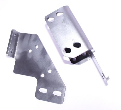
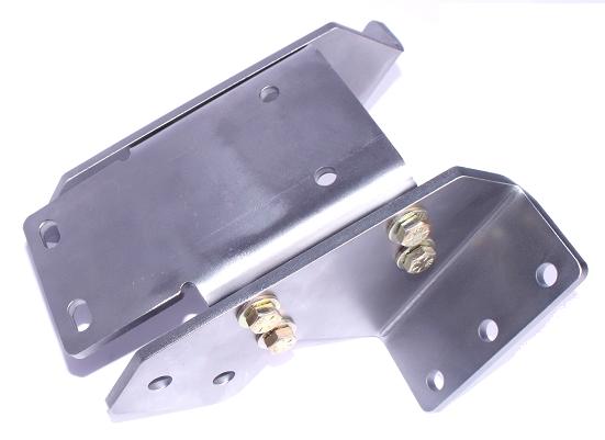
Locate the engine mount pads that are marked "P" and "D". The "P" is the passenger side and the "D" is the drivers side.
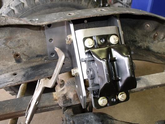
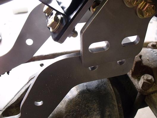
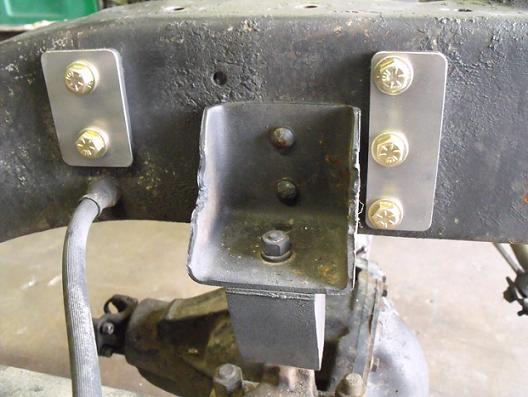
The picture below is showing the "D" drivers side and the drivers side rear plate.
The rear plates have slotted holes on the bottom and two holes that bolt the plate to the frame.
The rear sides of the mount pads have slotted holes, the front holes in the mount pads are not slotted.
Install 4 3/8 bolts through the rear plate into the mount pad using a washer on both sides and lock nuts.
Snug the nuts but do not tighten.
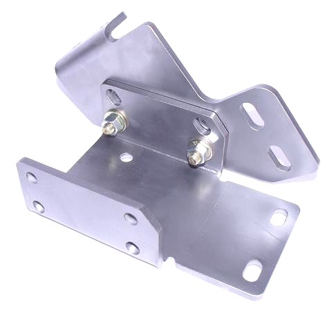
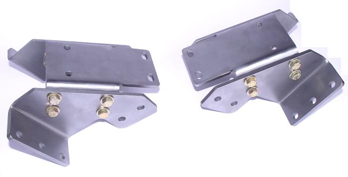
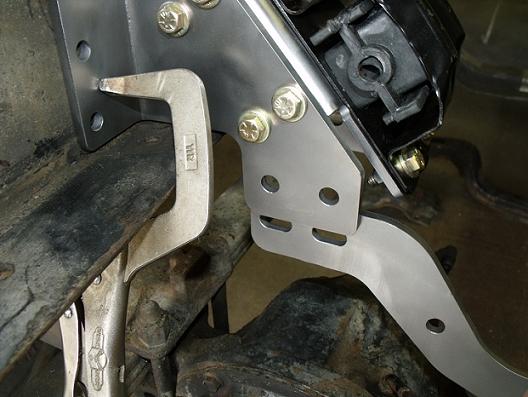
Install the front plates on the mount pads.
The lower holes are not slotted, nor are the front holes in the mount pads.
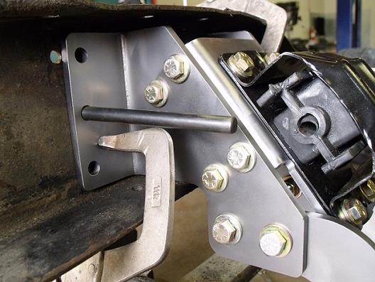
This is showing the drivers side assembled.
Snug the bolts enough so the plates will still move but do not tighten.
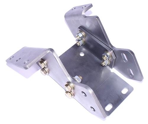
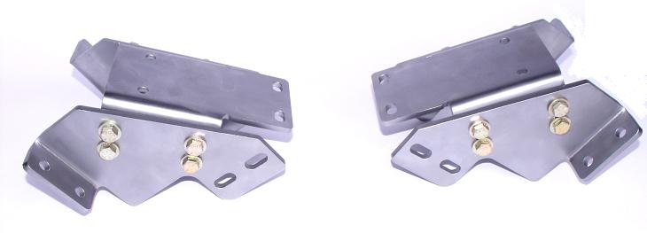
Next, assemble the "P" passenger side in the same manner.
The rear plate's four holes are slotted.
The rear plate has two bolts that bolt to the frame, the front plate has three bolts that bolt to the frame.
At this point, install your clam shell engine mounts to the frame pads using 3/8 bolts with a washer on both sides and lock nuts.
These bolts can be torqued to 32 ft lbs.
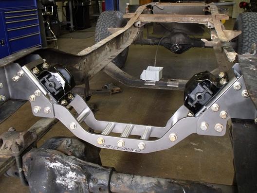
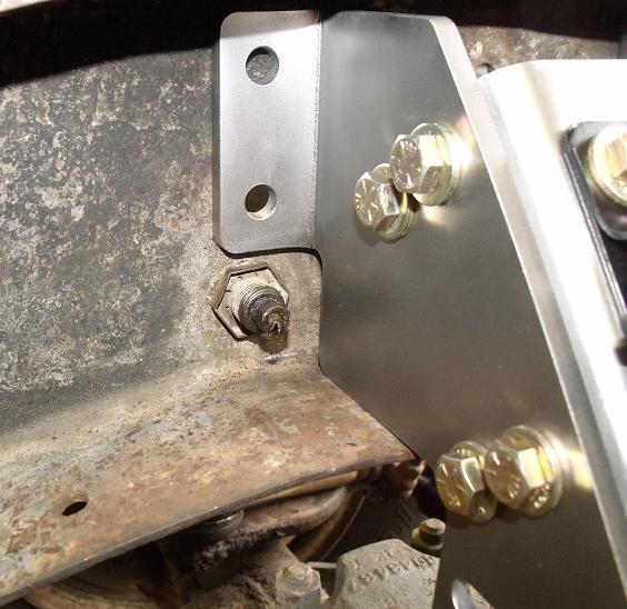
Place the assembled pieces against the inside of the frame on the corresponding sides.
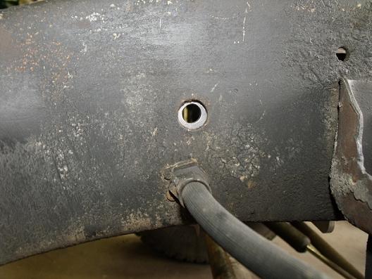
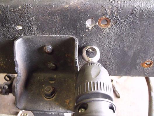
Most factory frames have an existing hole located above where the front brake lines run through the frame.
Center the bottom rear hole of the rear bracket on this hole.
(If this hole does not exist, you can place the holes in the rear bracket inline with the brake line.)
Place a temporary clamp on the front bracket clamping it to the frame on both sides.
At this point care should be taken to measure from the front sides of the assembly to the front of the frame.
Take several measurements to ensure that both sides are sitting evenly from the front of the frame or the front leaf spring perch holes.
There are several holes on both sides of the frame that are symmetrical that you can measure.
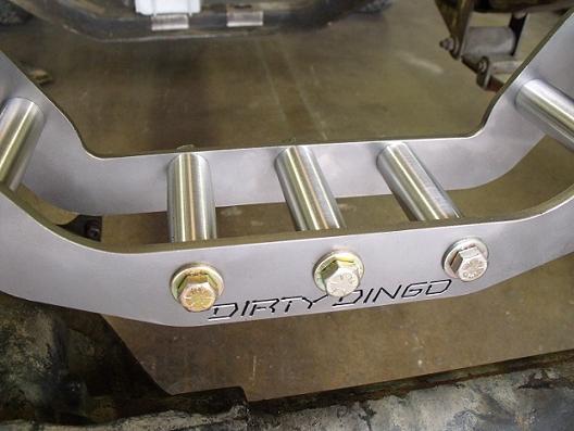
Next, bolt the lower cross member piece between the frame pad assemblies using 7/16 bolts, a washer on both sides and lock nuts.
Snug, do not tighten.
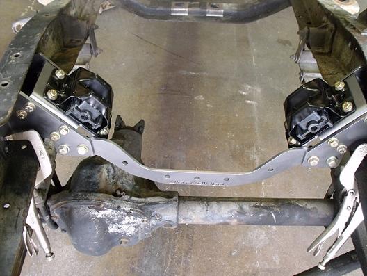
Then install the rear cross member using 7/16 bolts, washers on both sides and lock nuts.
Snug, do not tighten.
Install the billet spacers with 7/16 bolts, a washer on both sides and lock nuts.
These bolts can be tightened. Torque to 45 ft lbs.
With the frame pads and brackets square in the frame, mark the three holes in the front and the two holes in the rear.
Remove the center crossmember and remove the mount pad assemblies.
Drill holes using a 3/8 drill bit.
Chamfer newly drilled holes to reduce cracking.
Assemble frame pad assemblies back on frame using 3/8 bolts, a washer on both sides, the outer frame plates and lock nuts.
Snug, do not tighten.
Install center cross member assembly.
Snug the four 7/16 bolts on both sides.
At this point you can tighten the frame pads to the frame on both sides.
Tighten the four front and the four rear bolts on the mount pad assemblies.
Next, tighten the four 7/16 bolts on each side of the frame pad assembly to the cross member.
At this point all the bolts should be tight.